Realtime live display of the information the
electronic control unit of the selected vehicle system is currently
deriving from its input sensors.
- Feedback: Display of the current feedback fuelling
correction. This is shown as a percentage of the mapped (open loop)
value. This percentage is continuously updated by the MEMS ECU whenever
the conditions for closed loop fuelling are present. At other times, the
feedback value will show 100%, indicating that closed loop fuelling is
not operational. High values of feedback (e.g. 120%) indicate that
feedback is attempting to compensate for fuelling being too lean and low
values (e.g. 80%) for fuelling being too rich. Note: Misfire condition
will be shown as high values, as feedback will be fooled into
compensating for a system running too lean.
- Throttle angle: Shows the position of the throttle
disc obtained from the MEMS ECU using the throttle potentiometer. This
value should change from a low value to a high value as the throttle
pedal is depressed.
- Throttle bits: This value shows the signal received
by the ECU from the Throttle Position Sensor (Throttle Pot). The value
is displayed in bits and has a range from 0(closed) to 255(open). The
full range of values will not be seen in practice.
- Stepper position: Shows the position of the IACV
stepper motor as calculated by the ECU. The ECU has no method of
actually measuring this position but instead works it out by remembering
how may steps it has moved the stepper since the last time the ignition
was switched off. If a stepper motor fault exists, this number will be
incorrect. This value will normally be changing during idle condition as
the ECU makes minor changes to the idle speed. A value of 0 during idle
conditions indicates a fault condition or poor adjustment, as does a
very high value.
- Idle setpoints: If an idle service offset has been
set up in this ECU, the offset from the normal idle RPM is shown here.
Normally, only two values will ever be displayed. 0 RPM or 49 RPM. The
offset can be set up using the function found in the OTHER section.
- Hot idle position: This is the number of IACV steps
from fully closed (0) which the ECU has learned as the correct position
to maintain the target idle speed with a fully warmed up engine. If this
value is outside the range 10 - 50 steps, then this is an indication of
a possible fault condition or poor adjustment. This value can be forced
for a short time using the function in the settings section.
- Idle speed error: This is the current difference
between the target idle speed set by the MEMS ECU and the actual engine
speed. A value of more than 100 RPM indicates that the ECU is not in
control of the idle speed. This indicates a possible fault condition. A
quick addition of this value and the current engine RPM will also tell
what the value is of the ECU's target Idle Speed.
- Idle runline: This is the number of steps from 0
which the ECU will use as guide for starting idle speed control during
engine warm up. The value will start at quite a high value (>100
steps) on a very cold engine and fall to < 50 steps on a fully warm
engine. A high value on a fully warm engine or a low value on a cold
engine will cause poor idle speed control. Idle run line position is
calculated by the ECU using the engine coolant temperature sensor.
- Ignition advance: This is a facility which is built
into the MEMS ECU to overcome some situations during the service life of
a vehicle where it might be wished to eradicate a problem such as a low
octane fuel being constantly used or engine wear by slightly advancing
the ignition timing. the idle speed of the engine. The function can be
removed by resetting the adaptive values.
- Ignition advance offset: Shows the value of the
service ignition offset currently being used by the MEMS ECU. This is a
special service adjustment for countries which use low octane fuel. The
value is set by the Service Ignition Offset found in the OTHER section
and can be cleared by using the Reset Adaptations function found in the
same section.
- Coil charge: This is the time for the ignition coil
to charge up to its specified current, as measured by the MEMS ECU. With
a battery voltage of about 14V, this value should be about 2-3mS. A high
value for coil charge time may indicate a problem with the ignition coil
primary circuit.
- Oxygen sensor status: Shows the state of MEMS
internal diagnostics on the oxygen sensor and its associated wiring. A
displayed value of ON indicates no fault. A displayed value of OFF
indicates a possible problem.
- Throttle switch: Shows the state of the throttle
switch (if fitted). On systems without an actual throttle switch the
value shown indicates whether the MEMS ECU has calculated that the
throttle is closed by using the throttle position sensor. If the switch
shows 'ON' when the throttle is closed, then the vehicle will not idle
correctly and the closed throttle position may need to be reset. This
procedure is performed by fully depressing and releasing the accelerator
pedal 5 times within 10 or less seconds of turning on the ignition and
then waiting 20 seconds.
- Park/neutral switch: This shows the state of the
park neutral switch as measured by the MEMS ECU. This switch is used to
improve the quality of engine idle speed control on automatic or CVT
(Constantly Variable Transmission) gearbox vehicles. A fault with this
switch will cause the idle speed to dip or rise suddenly when the gear
selection is changed between neutral and drive. This display will not
work on manual gearbox vehicles.
- Air con switch: This shows the state of the air
conditioning request signal at the MEMS ECU. This signal depends on the
state of the air conditioning switch, the blower fan control, the air
conditioning thermal switch and the trinary high/low pressure switch.
The ECU will not show air conditioning on unless all of these switches
are on. The thermal switch will be off if the temperature of the air
leaving the evaporator is less than about 3C and the high/low pressure
switch will be off if the pressure of the refrigerant is too high or too
low.
- Trinary switch: This shows the ECU high fan request
input. This input will be active if the air conditioning trinary medium
pressure switch is closed requesting that the ECU fan control is set to
maximum (fans on high speed).
- Ignition switch: Shows the state (ON/OFF) of the
ignition switch as read by the MEMS ECU. Depending on the vehicle type,
errors in reading the ignition switch may lead to cutting out, failure
to power down (causing flat battery) or failure to start.
- Fuel rail temperature: This shows the temperature
measured by the ECU using the fuel rail temperature sensor (if fitted).
If the sensor is open circuit, then a fixed default value will be
displayed. The fuel rail temperature is used by the ECU as an aid to hot
starting and to make corrections to fuelling. If the sensor is not
operating correctly hot starting and engine performance may be impaired
slightly. On MEMS ECUs which don't support this sensor the value will
display N/S.
- Ambient temperature: This shows the temperature
measured by the ECU using the ambient air temperature sensor (if
fitted). If the sensor is open circuit then a fixed default value will
be displayed. The sensor is used by the ECU to measure the air
temperature in the engine bay. This is usually done to control an extra
engine bay cooling fan on vehicles which require this. The effect of a
faulty sensor is normally incorrect operation of the engine bay cooling
fan. On MEMS ECUs which don't support this sensor the value will display
N/S.
- Coolant temperature: This shows the coolant
temperature as measured by the ECU. If the sensor is open circuit, a
default value of about 60C will be displayed. During engine warm up, the
value should rise smoothly from ambient to approximately 90C. Sensor
faults may cause several symptoms including poor starting, fast idle
speed, poor fuel consumption and cooling fans running continuously.
- Inlet air temperature: This shows the temperature
measured by the ECU using the inlet air temperature sensor (if fitted).
If the sensor is open circuit, then a fixed default value will be
displayed. The inlet air temperature is used by the ECU to retard the
ignition timing to avoid knock and trim the fuelling when hot. If the
sensor is not operating correctly the engine performance may be impaired
slightly.
- Jack count: On systems using a throttle body where
the idle air is controlled by a stepper motor which directly acts on the
throttle disk (normally metal inlet manifold), the count indicates the
number of times the ECU has had to re-learn the relationship between the
stepper position and the throttle position. If this count is high or
increments each time the ignition is turned off, then there may be a
problem with the stepper motor, throttle cable adjustment or the
throttle pot. On systems using a plastic throttle body/manifold, the
count is a warning that the MEMS ECU has never seen the throttle fully
closed. The count is increased for each journey with no closed throttle,
indicating a throttle adjustment problem.
- Loop status: This shows whether the fuelling is
being controlled using feedback from the oxygen sensors. A displayed
value of ON indicates that closed loop fuelling is active, a displayed
value of OFF indicates fuelling open loop. On a fully warm vehicle, Loop
Status should indicate closed loop under most driving and idling
conditions.
- Battery volts: This shows the voltage of the
vehicle supply measured internally by the ECU. Large errors in this
measurement will lead to possible poor starting and errors in idle CO.
- Injector time: This is the value, in microseconds,
of the correction trim value of the fuel injection time currently being
used by the MEMS ECU. This value is mainly used to adjust the idle
fuelling. The value of Injector time is normally an adaptive value which
is set up automatically by the ECU on vehicles fitted with an oxygen
sensor. However, for vehicles not equipped with an Oxygen sensor, this
value must be adjusted manually to obtain the correct fuelling. This is
done in the Settings section.
- Oxygen sensor volts: This shows the voltage across
the oxygen sensor as read by the MEMS ECU. Once the engine is fully
warm, during most idle and driving conditions, this voltage will switch
rapidly between a value between 0.0v-0.2v to a value between 0.7v and
1.0v. The sensor detects the presence or absence of oxygen in the
exhaust gas. When the exhaust gas has oxygen present the ECU will read a
low voltage.
- Manifold pressure: Shows the pressure measure by
the internal MEMS air pressure sensor. This value should show
atmospheric pressure of 100 KPa when the engine is stopped and a lower
value between 25 - 40 KPa during engine idle conditions. Very high
values may indicate problems with the sensor inside the MEMS or more
likely a blocked or disconnected vacuum pipe. Moderately raised values
may indicate mechanical problems with the engine.
- Engine speed: The rotational speed of the engine
calculated by the MEMS ECU using the crankshaft sensor. Faults in the
crankshaft sensor or associated wiring may be indicated if this display
reads 0 during engine cranking.
|
 LUCAS MEMS
1.6/1.9 - System Overview
LUCAS MEMS
1.6/1.9 - System Overview LUCAS MEMS
1.6/1.9 - Known Fitments
LUCAS MEMS
1.6/1.9 - Known Fitments LUCAS MEMS
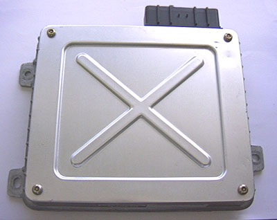
1.6/1.9 - Physical Details
LUCAS MEMS
1.6/1.9 - Physical Details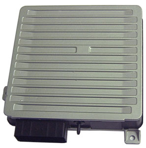
 LUCAS MEMS 1.6/1.9
- Pin Outs
LUCAS MEMS 1.6/1.9
- Pin Outs
